CARDDECK SHEAR |
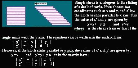
Simple shear is analogous to the sliding of a deck of cards. If we choose two coordinates such as x and y, and allow the block to slide parallel to x axis, then the value of x' and y' are given by
x'=x+gx and y'=y
where g is the shear strain or tan of the angle made with the y axis. The equation can be written in the matrix form:
| x' | = | x | | 1 -g |
| y' | = | y | | 0 1 |
However, if the block slides parallel to y axis, the values of x' and y' are given by:
x'=x and y'=y+gy or in the matrix form:
| x' | = | x | | 1 0 |
| y' | = | y | | -g 1 |
In the first set of figures below, you will notice that the lines in the grid parallel to x axis have not changed in length after homogeneous deformation but those parallel to y have increased in length. The lines parallel to x have therefore not changed length and are indeed LINES OF NO FINITE LONGITUDINAL STRAIN. The deformation is HOMOGENEOUS SIMPLE SHEAR since parallel and rectilinear lines maintain their parallelism and rectilinearity even after deformation. These lines are the lines along which maximum displacement or shear has occurred. These lines could be considered to be the trajectories of shear planes such as cards in a card deck. In any direction not parallel to these lines, the amount of shear is of lesser magnitude. In the figure at the bottom, in the second block or set at top right, the grid implanted has lines that make angle of 45° with both x and y axes. After deformation, lines of one set have increased in length while those of the other set have decreased. The lines of maximum shear parallel to x are not drawn but the shear is maximum parallel to x. In other words, in nature, the flow by shear can occur in a given direction but the discrete shear planes may or may not be actually visible. The lines that have shortened are in fact parallel to maximum principal compressive stress s1 and parallel to this direction extension fissures could be expected to develop. If we implant a circle in the undeformed initial grid, this will be transformed into an ellipse with the long axis of the ellipse parallel to the lines that have increased in length. In other words, these lines may be parallel to the 1+e1 direction and the set may actually define the trajectories of cleavage planes or l1l2 planes. Thus the shortened lines make an angle of 45° with the shear direction, while the extended ones an angle of 135° .
The lower part of the figure shows inhomogeneous deformation. In the left hand side block, the grid has lines
parallel to x and y but you will notice that the lines parallel to x have not changed in length. They also are rectilinear since the longitudinal strain along the x direction is zero. But the lines initially parallel to y have become curved and any one continuous line makes lesser and lesser angle with x as it goes inward towards the centre. This is HETEROGENEOUS OR INHOMOGENEOUS SIMPLE SHEAR. In other words the amount of shear increases towards the centre as the left hand sigmidally curved margin chords make higher angles with x away from the centre but smaller as the central part is approached. The bisectors of the acute angles of individual parallelograms define the long axes of the ellipses that would be produced if we implant circles in original square grids. But the strain is uniform all over the body. The right hand figure block shows the oblique grid with both sets of lines making an angle of 45° with x and y axes. Lines of one set have the cumulative length shortened since they fall in the negative extensional areas of the strain ellipses and are actually folded. The lines of the other set have increased in length or boudinaged. They are also more or less sigmoidally curved. This is because these join the long axes of individual ellipses. The cleavage would form parallel to the planes whose trajectories these lines are and therefore you would always find sigmoidal cleavage in SHEAR ZONES or in areas where the deformation has progressed by heterogeneous simple shear. Shear zones generally have undeformed wall rocks though this may not always be true. The angle q ' or the cleavage trace or 1+e1 and boundaries of shear zones or planes of shear can be used to compute the amount of shear strain if the deformation is volume conserving by:
g = 2 /(tan 2 q ')
If the deformation is by plane simple shear, then the values of principal strains !+e1 or 1+e3 (the value of 1+e2 being equal to unity) could be given by the equation in the quadratic form which has two roots, both positive:
Öl1 or Öl2= [(g2+2)±(g{g2+4}1/2)/2]1/2